Here is the link to our Presentation 1:
https://docs.google.com/presentation/d/17jWUimgnZD5Ax67Z1MixaxjqK4BDnnuSh3bH8uC3pDk/edit?usp=sharing
We had a good presentation, including what we've been working on all semester, our deliverables, schedule, and difficulties in completion. Our difficulties still remain:
1. We are waiting on Andries' blueprint to construct our column stub from Vander-Bend
2. We haven't finished clamp designs, so we can't get those 3D printed yet
3. We can't machine our wooden columns until Claude decides what dimensions he wants
Ultimately, there were hardly any questions on our presentation, so we think we were successful on that.
Wednesday, March 1, 2017

Tuesday, February 28, 2017
Week 18 Progress (2017-3-1)
On Saturday, February 25, the group met up with Eric Rosenfeld in the library. He explained some of the information from his summer research work, explaining how we could integrate the solar panels onto our possible designs for the Superway guideway.

For this image, Design #1 from Week 16 Progress, Eric mentioned that Snaprack probably wouldn't be able to attach onto the steep curve of the top bar. He suggested that we could do thin film (which has 17% efficiency), Standard Solar, or solar glazing.
He also spoke of the bogey team's work, because they use DC components with different lanes while AC uses an entire long line of components. The DC power needs an inverter while AC needs transformers. (And I apologize if this isn't explained correctly; none of us are too skilled in electronics) Currently, Wayside utilizes AC while the pod is DC (so it needs a transformer). We were playing around with the idea of the electronics fitting into that empty space on our column-rod designs, but it ultimately depends on the wayside and bogey teams. We thought of maybe placing the transformer underground and running wires to the electric components, but that wouldn't be as good for the pods.
Other than this meeting, we finished our Presentation 1, which will be viewable on next week's blog post.
Wednesday, February 22, 2017
Week 17 Progress (2017-2-22)
This week has culminated into a collaboration with outside sources. Using the designs that we've already come up with, we've contacted Eric Rosenfeld for advice regarding positioning of the solar panels on the top of the guideway.
He says there are four basic design concepts that he's considering: a sloped design, taking the design concept of Ron Swenson's Plantronics solar canopy installation, pitched roofs, flat roof design in which commercial racking system can be used, and ground mounts. He recommends SnapnRack, which attaches via screws but has systems that make it easier to remove and maintain.
After looking over Claude's and Andries' concepts for the column and guideway design, he suggests that it could utilize the sloped design with a central support, though he thinks a four support point design may be more sturdy. He worries that not many roads have islands in the center that we can place these supports into. Hence, he hasn't solidified a solar racking design because we haven't solidified a track design. Whatever orientation we make the top of the track have, the solar panels will have to adapt to.
While developing, we will need to let Eric know the distance between supports so he can develop a better racking system. Dr. Furman says the current design concept uses beams that are 24 meters apart, though we haven't really decided on that exact value yet.
Here are some options he's given us:


He says there are four basic design concepts that he's considering: a sloped design, taking the design concept of Ron Swenson's Plantronics solar canopy installation, pitched roofs, flat roof design in which commercial racking system can be used, and ground mounts. He recommends SnapnRack, which attaches via screws but has systems that make it easier to remove and maintain.
After looking over Claude's and Andries' concepts for the column and guideway design, he suggests that it could utilize the sloped design with a central support, though he thinks a four support point design may be more sturdy. He worries that not many roads have islands in the center that we can place these supports into. Hence, he hasn't solidified a solar racking design because we haven't solidified a track design. Whatever orientation we make the top of the track have, the solar panels will have to adapt to.
While developing, we will need to let Eric know the distance between supports so he can develop a better racking system. Dr. Furman says the current design concept uses beams that are 24 meters apart, though we haven't really decided on that exact value yet.
Here are some options he's given us:
- a truss system will allow us to put more of the solar module weight on the track support beams and trusses, and less on the roof of the transit
- a thin-film canopy, which can be printed at any length, but he's unsure of how it will handle San Jose weather conditions
He also answered a previous question of ours. For the weight of the modules, he was previously considering SunEdison-R360EzC-4y module with a nominal power of 360.192W, efficiency 18.42%, approximately 22kg, at approximately 0.63 center per Watt. The modules are 1976mm x 990mm x 50mm. We need approximately 19,600 modules to run 88 pods for an entire year, assuming no alterations made. [https://cngsolarengineering.com/wp-content/uploads/2015/02/SUNEDISON-%E2%80%93-R335-360.pdf]
Besides communication with Eric, Claude has resumed communication with Andries, asking for blueprints for a 4 foot long section of interlocking column, with estimations about its properties, as well as suggestions about potential connector designs. Our team will be attempting to meet up with Eric sometime this weekend or next. In addition, we will be working on our Presentation 1 soon.
Tuesday, February 14, 2017
Week 16 Progress (2/15/17)


Claude has also been exploring a potential alternate design that could take advantage of the main column's shape and strength.They are shown below and more details can be seen in his blog post.


Tuesday, February 7, 2017
Week 15 Progress (2/8/17)
For the first week of the spring semester we were given new information about what we would need to do.
At the beginning of the session, we had a discussion with Andries about his x-column designs, and he answered many of our questions.
Towards the end, we also had a meeting to discuss what we were expected to complete for this semester. At first, we thought we would need to manufacture the columns and assemble a large T-shaped working prototype. However, we learned that a client wanted a round and curved Y-shaped version. Also, Andries stated that we would likely be better making a miniature working model to show what the completed project would look like, as well as having Vander-Bend manufacture a short version of a full scale column to showcase the technology. He also offered to have his team make the official manufacturing blueprints when we finalize the dimensions.
From here on, we will start by designing a column structure and guideway on some computer-assisted drafting technology to portray an aesthetically-pleasing architectural model of the Y-shaped structure. Once we have basic dimensions, Andries' team will be able to convert our design into exact measurements, which we will send to Vander-Bend for prototype production. This model will simplify our contact's bogie system and switching track.
At the beginning of the session, we had a discussion with Andries about his x-column designs, and he answered many of our questions.
Towards the end, we also had a meeting to discuss what we were expected to complete for this semester. At first, we thought we would need to manufacture the columns and assemble a large T-shaped working prototype. However, we learned that a client wanted a round and curved Y-shaped version. Also, Andries stated that we would likely be better making a miniature working model to show what the completed project would look like, as well as having Vander-Bend manufacture a short version of a full scale column to showcase the technology. He also offered to have his team make the official manufacturing blueprints when we finalize the dimensions.
From here on, we will start by designing a column structure and guideway on some computer-assisted drafting technology to portray an aesthetically-pleasing architectural model of the Y-shaped structure. Once we have basic dimensions, Andries' team will be able to convert our design into exact measurements, which we will send to Vander-Bend for prototype production. This model will simplify our contact's bogie system and switching track.
Thursday, December 1, 2016
Week 14 Progress (12/7/16)
On 11/30, we had our last presentation. It can be viewed in the following link. Note that this is the version that is appropriate to share to the public, so a few slides may be missing confidential information/pictures.
https://docs.google.com/presentation/d/17l4xqHgoxLce8Vdu_gyxHQQ303cRC3ZKxc033v33_WI/edit?usp=sharing
On 12/2, the first draft of our final report is due. We are working diligently to make sure that we meet this deadline.
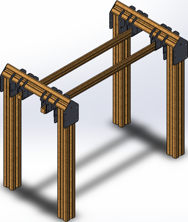
This week, we are focusing wholeheartedly on our final prototype. Winter bought materials from Home Depot and is going to be milling them (possibly with Kevin's help) on Friday. Claude was originally planning on 3D printing the clamps to be used in our design, but it appears that laser cutting is more time efficient and productive. Winter also bought quikrete that will be used for the footings, but we haven't yet found a base to put the feet of the structure into so that the quikrete can be poured. Ultimately there are a lot of loose ends, but we should have out prototype completed within the week.
UPDATE:
Here are pictures of the progress on the prototype.


We decided to use concrete from the civil lab instead of quikrete so we could practice for next semester's prototype. We didn't get the clamps created in time for the last official class meeting, but all the CAD models are complete and ready to be laser-cut, and the model could be completed early in the spring semester if requested.

https://docs.google.com/presentation/d/17l4xqHgoxLce8Vdu_gyxHQQ303cRC3ZKxc033v33_WI/edit?usp=sharing
On 12/2, the first draft of our final report is due. We are working diligently to make sure that we meet this deadline.
This week, we are focusing wholeheartedly on our final prototype. Winter bought materials from Home Depot and is going to be milling them (possibly with Kevin's help) on Friday. Claude was originally planning on 3D printing the clamps to be used in our design, but it appears that laser cutting is more time efficient and productive. Winter also bought quikrete that will be used for the footings, but we haven't yet found a base to put the feet of the structure into so that the quikrete can be poured. Ultimately there are a lot of loose ends, but we should have out prototype completed within the week.
UPDATE:
Here are pictures of the progress on the prototype.
We decided to use concrete from the civil lab instead of quikrete so we could practice for next semester's prototype. We didn't get the clamps created in time for the last official class meeting, but all the CAD models are complete and ready to be laser-cut, and the model could be completed early in the spring semester if requested.
Monday, November 28, 2016
Week 12 + 13 Progress (11/23-30/16)
For the week of 11/16 to 11/23, we finished our second rapid prototype. This model utilized a thicker cardstock material and our goal was to portray how a longer column structure would be built. The pieces interlap and interlock similar to a puzzle, with opposite sides reinforcing each other.


The left picture is a side view of the column. You can see that the structure is brick-like in placement of the interlocking pieces. The right is a top view, where the structural integrity is visible. Once the column is filled with concrete, it would then be extremely solid and strong.
Our rapid prototype was just a quick model so that we could have something tangible for Dr. Furman and Ron to see and show off to sponsors and other companies. Otherwise, our entire week was dedicated to the fabrication and construction of this simple model, which really takes more time to make than would seem. Our next model will be more of a depiction of how the clamping mechanisms would attach the column to the footings and to the guideway.
On 11/18, we met with Scott Bryant at Vander-Bend to discuss possible manufacturing of our model, any questions we had, and we received a tour of the site. Here is what we learned:
- Our model will be laser cut, since we want a thickness of around 3 mm which is about 1/8 inch steel. Their laser cutters can cut up to 3/8 thickness, if thicker, water-cutting is utilized.
- The laser cutters accomodate up to 60x120 inches of material. This is more than the typical standard of 48x120.
- Vander-Bend doesn't handle casting painting, injection molding, etc. -type services.
- They manufacture a lot for the hospital industry, fuel cells, fruit industry, etc.
- We will make a model of what we need constructed on SolidWorks. We will construct the 3D model of it so that they can assemble as portrayed. They will need the step file and drawing.
- Our model will be cold-rolled steel, either 10-10 or 10-08. Bend radius of 1/32 inch.
- Claude will talk with Andres.
- Manufacture time will be at least 3 weeks, so we need to plan around that.
For the week of 11/23 to 11/30, we are focusing on our end-of-semester prototype while enjoying our Thanksgiving break with our families. We need to work on our Bill of Materials, so therefore we need to figure out all of the material we need to obtain for our prototype for the class.
Subscribe to:
Posts (Atom)