This week is much slower, since we pretty much have the bulk of our presentation finished, yet we will be presenting November 2nd. We will be meeting with Ron, Dr. Furman, and Eric on Monday to get further guidance and help on our calculations.
Claude will be finishing taping up our rapid prototype, which should be ready to present soon.
[insert picture of rapid prototype]
We are also coordinating a meeting with Vander-Bend this upcoming week with one of the 1/12th scale teams. We will ask any questions we might have for when we construct our full-sized prototype.
Thursday, October 27, 2016

Tuesday, October 25, 2016
Week 8 Progress (10/26/16)
This week, we have mainly been preparing for our presentation. Here is the breakdown so far for the presentation who-will-do-what:
Theoretical/Analysis
- Kathlyn - thermal analysis, expansion joint gap, properties of strong steel
- Kevin - loading for column and beam
- Isaac - ANSYS analysis for loads?
Project Schedule and Deliverables
- Winter
For Project/Problem Status and Initial Designs/Comparisons of Alternatives, we will all work on this, though Winter and Claude will input more information.
Finally, thanks to Dr. Furman's instructions to the IT guys, the laser cutter on campus finally works. We were able to cut out our rapid prototype (thanks to all of Claude's work) and we will hopefully assemble it before the presentation, which might be tomorrow.
 |
| Pieces of our rapid prototype, not yet assembled |
Furthermore, since we've lost some sense of direction due to all of the unknown variables, we are working on changing the scope of our group. From full-scale, hopefully we will be able to just focus on columns, beams, and footings, analyzing materials and joining processes. We are focusing more on the structural aspect of Spartan Superway at this point, so our models will probably need to be closer to 1/12 scale to be reasonable for our group. We plan on using MDF for our end-of-semester prototype, and high-strength steel for next semester.
Wednesday, October 19, 2016
Week 7 Progress (10/19/16)
We progressed by meeting with Ron Swenson and Dr. Furman to discuss how our contact in Africa has progressed on their rapid transit system. We watched their presentation to gain more perspective on how the railways are designed and supported. For example, originally we thought we would be attaching beams to the support columns by implementing a clamp system. However, now we need to research if we could design interlocking tabs instead.
To make the system ride more efficiently, we played around with the idea of two railways going one direction. One would be the main transport line, which would constantly move and stop at stations to pick up more people. The other line would be where idle cars sit until they're called upon at the next station.
This week we will be researching the following:
Claude - progression on acquiring laser cutter software for rapid prototype [Epilogue Helix]
Winter - measuring widths of streets and sidewalks across San Jose
Kathlyn - researching properties of steel for expansion joins (from pamplet)
Kevin - research on something else?
Isaac - MIA
Sunday, October 9, 2016
Week 6 Progress (10/12/16)
This week, we gave our presentation on the progress we've made so far regarding the full scale test track improvements and plans.. Here is the link to it, along with our comments:
https://docs.google.com/presentation/d/1in1OkRoP68i6vTJtyP6Aq-7OXTKatwIKRJhSLFXtZcs/edit?usp=sharing
Regarding new research, we developed our rapid prototype that we will construct as soon as we have access to the ME lab in the engineering building. We will be laser-cutting an interlocking column out of construction paper to inspect how it will fit together. The design resembles somewhat of a Solomon's knot, interlocking in several places for support. However, we are unable to share the prototype sketch due to confidentiality conflicts.

For next week, we will gather more information regarding cables used in bridges, as well as expansion joints. At some point, we will need to measure the existing full scale track to gather dimensions.
https://docs.google.com/presentation/d/1in1OkRoP68i6vTJtyP6Aq-7OXTKatwIKRJhSLFXtZcs/edit?usp=sharing
Regarding new research, we developed our rapid prototype that we will construct as soon as we have access to the ME lab in the engineering building. We will be laser-cutting an interlocking column out of construction paper to inspect how it will fit together. The design resembles somewhat of a Solomon's knot, interlocking in several places for support. However, we are unable to share the prototype sketch due to confidentiality conflicts.
For next week, we will gather more information regarding cables used in bridges, as well as expansion joints. At some point, we will need to measure the existing full scale track to gather dimensions.
Sunday, October 2, 2016
Week 5 Progress (10/5/16)
This week, we began plans for rapid prototyping. Although our current design is still in progress, it would still be beneficial to have an actual physical model to facilitate the visualization of the guideway system and do some preliminary torsional testing. Because we don't have all the details regarding [our contact]'s design, Eric advised us to use the school's laser CNC machine to cut a model out of cardstock or cardboard as a means to better understand it. We plan to follow his advice and construct and test a section of [our contact]'s guideway support, and perhaps a variation of columns as well.
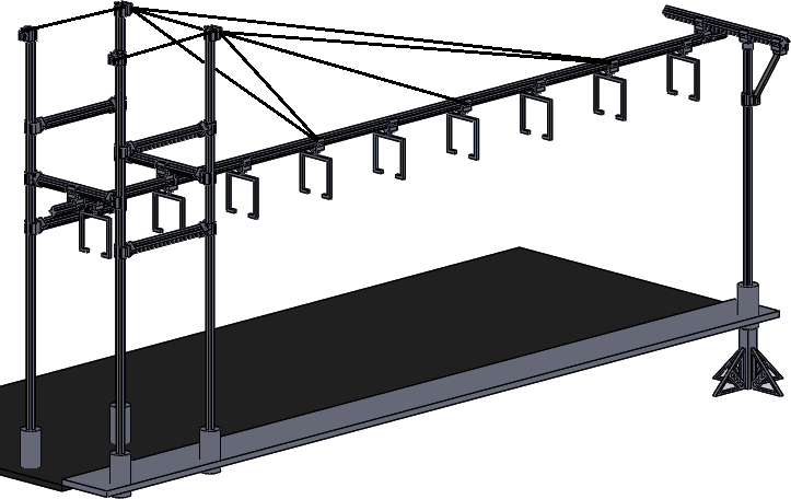
In addition, we also prepared for this week's upcoming presentation. During preparation, we began to focus in on the many aspects of this project demands and were consequently able to specifically delegate each member with separate responsibilities. The current responsibilities are as follows:
Claude - Design: Solidworks Deliverables
Isaac - Research/Calculations: Suspension/Footings
Kevin - Materials: Types of Materials/Ordering Materials
Winter - Testing: Torsional/Vibrations
Kathlyn - Research/Calculations: Thermal Expansion/Columns
Finally, we will further refine our presentation in time for class on Wednesday. We will also be getting more information from Ron on the South African system when he returns this week.
Our team's current design
In addition, we also prepared for this week's upcoming presentation. During preparation, we began to focus in on the many aspects of this project demands and were consequently able to specifically delegate each member with separate responsibilities. The current responsibilities are as follows:
Claude - Design: Solidworks Deliverables
Isaac - Research/Calculations: Suspension/Footings
Kevin - Materials: Types of Materials/Ordering Materials
Winter - Testing: Torsional/Vibrations
Kathlyn - Research/Calculations: Thermal Expansion/Columns
Finally, we will further refine our presentation in time for class on Wednesday. We will also be getting more information from Ron on the South African system when he returns this week.
Monday, September 26, 2016
Week 4 Progress (9/28/16)
During our fourth week gathering, we came together and collaborated on which of our SolidWorks designs would be the best route to take for our full scale guideway project. We decided on using Claude's design for the most part, using elements from Winter's footings and perhaps some of Kathlyn's support trusses.
We discussed furthering our knowledge of expansion joints and monorails, though this is a step we will take in more detail later in the project process. For a starting point for expansion joints, Isaac found this site: http://www.magebausa.com/en/794/Infrastructure/Division.htm which specializes in quiet and earthquake-proof expansion joints. We don't think this approach will be acceptable for our design, though.
Finally, we will prepare for our presentation, which we anticipate being next week. We've decided to each focus on a different guideline of Presentation #1 and we will collaborate on Tuesday, 9/27.
- #1 - Claude
- #2+3 - Kathlyn and Kevin
- #4 - Isaac
- #5 - Winter
- #6+7 - everyone
Tuesday, September 20, 2016
Week 3 Progress (9/21/16)
This week, we thought of more ideas that the new track and support system could look like. Upon meeting with Ron, we brainstormed some questions to ask to our contact in South Africa. Ron will update us when he returns from his Europe trip in a couple weeks. We also obtained several drawings from our contact which are not yet revealed for public use.
The first task we need to deal with is preventing track collapse should a column be hit by a vehicle. Here are some possible prevention tactics:
1. Build concrete around the pillars
2. Build a square frame around the pillars
3. More warning signs around track
4. Slopes so that final impact by a car would be slowed and forces brought upwards
5. Build the beams into a building instead on roads
6. Let the affected beam break, have weight supported by other beams
7. Air bags around beams
8. Memory foam type material around beams
Our ultimate decision, after researching impact attenuators and utility poles, is to wrap the columns with some kind of foam material. Possibilities are ethafoam or HR Polyurethane. The soft material could be protected and held in place by aluminum or some type of covering.
For this upcoming week, each of us will design a possible prototype for the new support posts, footing, beams, etc. We'll assume the bogey design isn't changing while changing the rest of the guideway design. We will then collaborate to see which aspects of each design we like.
Subscribe to:
Posts (Atom)