Thursday, December 1, 2016

Week 14 Progress (12/7/16)

On 11/30, we had our last presentation. It can be viewed in the following link. Note that this is the version that is appropriate to share to the public, so a few slides may be missing confidential information/pictures.

https://docs.google.com/presentation/d/17l4xqHgoxLce8Vdu_gyxHQQ303cRC3ZKxc033v33_WI/edit?usp=sharing

On 12/2, the first draft of our final report is due. We are working diligently to make sure that we meet this deadline.

This week, we are focusing wholeheartedly on our final prototype. Winter bought materials from Home Depot and is going to be milling them (possibly with Kevin's help) on Friday. Claude was originally planning on 3D printing the clamps to be used in our design, but it appears that laser cutting is more time efficient and productive. Winter also bought quikrete that will be used for the footings, but we haven't yet found a base to put the feet of the structure into so that the quikrete can be poured. Ultimately there are a lot of loose ends, but we should have out prototype completed within the week.

UPDATE:
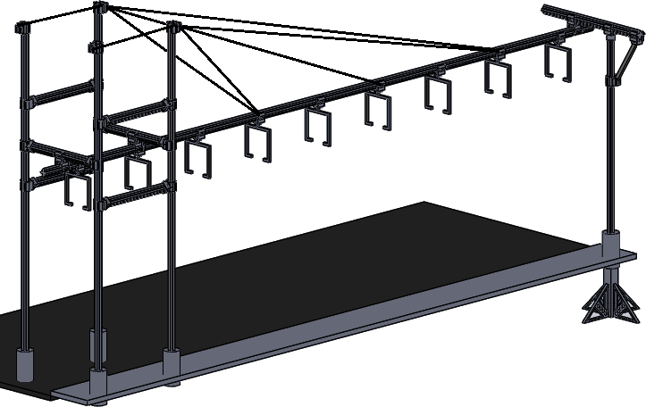
Here are pictures of the progress on the prototype.

We decided to use concrete from the civil lab instead of quikrete so we could practice for next semester's prototype. We didn't get the clamps created in time for the last official class meeting, but all the CAD models are complete and ready to be laser-cut, and the model could be completed early in the spring semester if requested.


Monday, November 28, 2016

Week 12 + 13 Progress (11/23-30/16)

For the week of 11/16 to 11/23, we finished our second rapid prototype. This model utilized a thicker cardstock material and our goal was to portray how a longer column structure would be built. The pieces interlap and interlock similar to a puzzle, with opposite sides reinforcing each other.

       
The left picture is a side view of the column. You can see that the structure is brick-like in placement of the interlocking pieces. The right is a top view, where the structural integrity is visible. Once the column is filled with concrete, it would then be extremely solid and strong.

Our rapid prototype was just a quick model so that we could have something tangible for Dr. Furman and Ron to see and show off to sponsors and other companies. Otherwise, our entire week was dedicated to the fabrication and construction of this simple model, which really takes more time to make than would seem. Our next model will be more of a depiction of how the clamping mechanisms would attach the column to the footings and to the guideway.

On 11/18, we met with Scott Bryant at Vander-Bend to discuss possible manufacturing of our model, any questions we had, and we received a tour of the site. Here is what we learned:
  • Our model will be laser cut, since we want a thickness of around 3 mm which is about 1/8 inch steel. Their laser cutters can cut up to 3/8 thickness, if thicker, water-cutting is utilized.
  • The laser cutters accomodate up to 60x120 inches of material. This is more than the typical standard of 48x120.
  • Vander-Bend doesn't handle casting painting, injection molding, etc. -type services.
  • They manufacture a lot for the hospital industry, fuel cells, fruit industry, etc.
  • We will make a model of what we need constructed on SolidWorks. We will construct the 3D model of it so that they can assemble as portrayed. They will need the step file and drawing.
  • Our model will be cold-rolled steel, either 10-10 or 10-08. Bend radius of 1/32 inch.
  • Claude will talk with Andres.
  • Manufacture time will be at least 3 weeks, so we need to plan around that.

For the week of 11/23 to 11/30, we are focusing on our end-of-semester prototype while enjoying our Thanksgiving break with our families. We need to work on our Bill of Materials, so therefore we need to figure out all of the material we need to obtain for our prototype for the class.

Tuesday, November 15, 2016

Week 11 Progress (11/16/16)

This week we focused on another rapid prototype that Ron wanted us to make. It is the same interlocking column design, but with overlapping parts "zippered" together, so that we can fabricate a longer version of a column. We've laser cut it and will hopefully have it assembled by tomorrow. Furthermore, Claude showed the rest of the team how to use the laser cutter, if any of us will need to use it in the future. In addition, he worked on the Solidworks design for the interlocking column that we're creating.

For our prototype, we will be making one out of MDF and one out of corrogated cardboard, or only one depending on remaining time. The guideway's beams and footings will be made out of MDF or 2x4. We will need to decide if we want to 3D print our connectors or not. We need to start thinking of ways to create our expansion joints.

Kevin and Kathlyn are working on designing the new footings. Isaac is still learning how to use ANSYS.

Monday, November 7, 2016

Week 10 Progress (11/9/16)

We gave our second presentation, which can be found at this link:
https://docs.google.com/a/saeedi.com/presentation/d/12QxQFgaVubvatXiafkcEsO_7_y-WWTLGiQzOiPLbLYI/edit?usp=sharing

This week, we are focused on our prototype. We have been in contact with AJ Snytsheuvel who is trying to coordinate a meeting with Vander-Bend. We hope that they might be able to help us construct our prototype out of whatever materials we decide.

For our prototype, we will probably utilize MDF or some thicker posterboard to fabricate our columns. The main focus of the prototype will be the footings and the methods necessary to connect footings, columns, and guideway together. We have a few potential methods to connect everything together:

  • clamp
  • bolted cantilever beam
  • attached sleeve
Other than that, we are mainly taking a rest from our presentation, and focusing on our upcoming writing assignment that will be due soon.

Thursday, October 27, 2016

Week 9 Progress (11/2/16)

This week is much slower, since we pretty much have the bulk of our presentation finished, yet we will be presenting November 2nd. We will be meeting with Ron, Dr. Furman, and Eric on Monday to get further guidance and help on our calculations.

Claude will be finishing taping up our rapid prototype, which should be ready to present soon.
[insert picture of rapid prototype]

We are also coordinating a meeting with Vander-Bend this upcoming week with one of the 1/12th scale teams. We will ask any questions we might have for when we construct our full-sized prototype.

Tuesday, October 25, 2016

Week 8 Progress (10/26/16)

This week, we have mainly been preparing for our presentation. Here is the breakdown so far for the presentation who-will-do-what:

Theoretical/Analysis
  • Kathlyn - thermal analysis, expansion joint gap, properties of strong steel
  • Kevin - loading for column and beam
  • Isaac - ANSYS analysis for loads?
Project Schedule and Deliverables
  • Winter
For Project/Problem Status and Initial Designs/Comparisons of Alternatives, we will all work on this, though Winter and Claude will input more information.

Finally, thanks to Dr. Furman's instructions to the IT guys, the laser cutter on campus finally works. We were able to cut out our rapid prototype (thanks to all of Claude's work) and we will hopefully assemble it before the presentation, which might be tomorrow.

Pieces of our rapid prototype, not yet assembled
Furthermore, since we've lost some sense of direction due to all of the unknown variables, we are working on changing the scope of our group. From full-scale, hopefully we will be able to just focus on columns, beams, and footings, analyzing materials and joining processes. We are focusing more on the structural aspect of Spartan Superway at this point, so our models will probably need to be closer to 1/12 scale to be reasonable for our group. We plan on using MDF for our end-of-semester prototype, and high-strength steel for next semester.

Wednesday, October 19, 2016

Week 7 Progress (10/19/16)

We progressed by meeting with Ron Swenson and Dr. Furman to discuss how our contact in Africa has progressed on their rapid transit system. We watched their presentation to gain more perspective on how the railways are designed and supported. For example, originally we thought we would be attaching beams to the support columns by implementing a clamp system. However, now we need to research if we could design interlocking tabs instead.

To make the system ride more efficiently, we played around with the idea of two railways going one direction. One would be the main transport line, which would constantly move and stop at stations to pick up more people. The other line would be where idle cars sit until they're called upon at the next station.

This week we will be researching the following:
Claude - progression on acquiring laser cutter software for rapid prototype [Epilogue Helix]
Winter - measuring widths of streets and sidewalks across San Jose
Kathlyn - researching properties of steel for expansion joins (from pamplet)
Kevin - research on something else?
Isaac - MIA

Sunday, October 9, 2016

Week 6 Progress (10/12/16)

This week, we gave our presentation on the progress we've made so far regarding the full scale test track improvements and plans.. Here is the link to it, along with our comments:
https://docs.google.com/presentation/d/1in1OkRoP68i6vTJtyP6Aq-7OXTKatwIKRJhSLFXtZcs/edit?usp=sharing

Regarding new research, we developed our rapid prototype that we will construct as soon as we have access to the ME lab in the engineering building. We will be laser-cutting an interlocking column out of construction paper to inspect how it will fit together. The design resembles somewhat of a Solomon's knot, interlocking in several places for support. However, we are unable to share the prototype sketch due to confidentiality conflicts.


For next week, we will gather more information regarding cables used in bridges, as well as expansion joints. At some point, we will need to measure the existing full scale track to gather dimensions.

Sunday, October 2, 2016

Week 5 Progress (10/5/16)

This week, we began plans for rapid prototyping. Although our current design is still in progress, it would still be beneficial to have an actual physical model to facilitate the visualization of the guideway system and do some preliminary torsional testing. Because we don't have all the details regarding [our contact]'s design, Eric advised us to use the school's laser CNC machine to cut a model out of cardstock or cardboard as a means to better understand it.  We plan to follow his advice and construct and test a section of [our contact]'s guideway support, and perhaps a variation of columns as well.


Street Example.png
Our team's current design

In addition, we also prepared for this week's upcoming presentation. During preparation, we began to focus in on the many aspects of this project demands and were consequently able to specifically delegate each member with separate responsibilities. The current responsibilities are as follows:

Claude - Design: Solidworks Deliverables
Isaac - Research/Calculations: Suspension/Footings
Kevin - Materials: Types of Materials/Ordering Materials
Winter - Testing: Torsional/Vibrations
Kathlyn - Research/Calculations: Thermal Expansion/Columns

Finally, we will further refine our presentation in time for class on Wednesday. We will also be getting more information from Ron on the South African system when he returns this week.

Monday, September 26, 2016

Week 4 Progress (9/28/16)

During our fourth week gathering, we came together and collaborated on which of our SolidWorks designs would be the best route to take for our full scale guideway project. We decided on using Claude's design for the most part, using elements from Winter's footings and perhaps some of Kathlyn's support trusses.

We discussed furthering our knowledge of expansion joints and monorails, though this is a step we will take in more detail later in the project process. For a starting point for expansion joints, Isaac found this site: http://www.magebausa.com/en/794/Infrastructure/Division.htm which specializes in quiet and earthquake-proof expansion joints. We don't think this approach will be acceptable for our design, though.

Finally, we will prepare for our presentation, which we anticipate being next week. We've decided to each focus on a different guideline of Presentation #1 and we will collaborate on Tuesday, 9/27.
  • #1 - Claude
  • #2+3 - Kathlyn and Kevin
  • #4 - Isaac
  • #5 - Winter
  • #6+7 - everyone

Tuesday, September 20, 2016

Week 3 Progress (9/21/16)

This week, we thought of more ideas that the new track and support system could look like. Upon meeting with Ron, we brainstormed some questions to ask to our contact in South Africa. Ron will update us when he returns from his Europe trip in a couple weeks. We also obtained several drawings from our contact which are not yet revealed for public use.

The first task we need to deal with is preventing track collapse should a column be hit by a vehicle. Here are some possible prevention tactics:

1. Build concrete around the pillars
2. Build a square frame around the pillars
3. More warning signs around track
4. Slopes so that final impact by a car would be slowed and forces brought upwards
5. Build the beams into a building instead on roads
6. Let the affected beam break, have weight supported by other beams
7. Air bags around beams
8. Memory foam type material around beams

Our ultimate decision, after researching impact attenuators and utility poles, is to wrap the columns with some kind of foam material. Possibilities are ethafoam or HR Polyurethane. The soft material could be protected and held in place by aluminum or some type of covering.

For this upcoming week, each of us will design a possible prototype for the new support posts, footing, beams, etc. We'll assume the bogey design isn't changing while changing the rest of the guideway design. We will then collaborate to see which aspects of each design we like.

Tuesday, September 13, 2016

Week 2 Progress (9/14/16)

We have officially identified our main tasks for this semester. We will need to design and construct a small section of full-scale guideway and test it for thermal expansion and contraction. We need to research manufacturing processes for producing the guideway, columns, footings, etc. The columns will be constructed similarly to how  a company in South Africa, constructed theirs. We will perform load testing and torsion testing. In addition, we'll develop expansion joints that will be tested for noise control.

So far, we've specified that we need to design a track that is 24 meters long, though we will probably only construct about 10 feet of track. The current track design is supported by a bracing on one side of the guideway, but we will probably implement a new idea where it's supported on both sides by a squared-horseshoe kind of bracket. Instead of the bracing and guideway being directly attached to the columns, they will be suspended vertically by some kind of ductile wiring, hopefully with a method that can dissipate and minimize vibrations (i.e shocks and sway) felt by the riders. In any case, more research on this must be done.

We will need to communicate with the half-scale and bogey teams, though their changes probably won't affect our version of the full-scale model in a major way. We will also need to communicate with the person working on the solar panel array since he will be directly impacted by our changes.

Below we have rough sketches of our thoughts and ideas. Figure 1, below, depicts already existing boogie apparatus and a potential bracing for extra support. The boogie apparatus in Figure 1 has already been created to be the primary boogie, so we must make our designs and decisions around the existing structures for the full scale track. Also in Figure 1, there's a light sketch of how we might want to suspend the tram to minimize vibrations. Figure 2, below, is a sketch of potential ideas but not much research behind any substantial supports, beams and bracing - mainly speculation.

 Figure 1. Rough sketch of existing structure            Figure 2. Sketch of potential beams/post/bracing


In addition, we've updated our Gantt Chart, which can be
found on our first post.


Monday, September 5, 2016

Full Scale Blog #1

Team Members/Skill:

Kevin Maligaya / CAD and design
Winter Saeedi / Solidworks, Acoustics, design
Kathlyn Garces / Solidworks, Autodesk, design
Claude Michel / Solidworks, Inventor, Creo

Contact Info:
Kevin - (510) 410-0889, kevinmaligaya@gmail.com
Winter - (925) 818-9424, winter@saeedi.com
Kathlyn - (209) 670-6034, kathlynmae.garces@gmail.com
Claude - (650) 430-3599, cm@mic4.net

Team Member Responsibilities:
All TBD for now.

Proposal narrative:
The intended goal of our project is to study the vibrations that occur within the test track, including joints, footings, and braces. We will strive to minimize movements (torsion) and reduce noise emissions through guided research and testing. Our preliminary design requirements are not clear at the moment until we receive further instruction.

Critical Path Schedule (gantter.com):

Updated 9/26/16

Budget:  Budget: $5,000-10,000 (very rough estimate)

Availability of Team:
Tuesdays, Thursdays after 3
Friday preferably before noon